You’re staring at a cracked assembly and asking why the rivet stem sheared or backed out after only months in service. You want to know whether the stem failure stole clamp force, sent metal fragments into the joint, or both. Most people assume a bent mandrel or poor material alone caused the problem and focus only on replacement parts.
This piece will show which failure modes actually cut fatigue life, how testing (pull‑out, lap‑shear, drop‑weight) reveals the root cause, and which specific fixes — alloy changes, tooling adjustments, inspection steps — restore clamp and keep debris out. You’ll leave knowing exactly which tests and fixes to prioritize. It’s simpler than it looks.
Key Takeaways
Here’s what actually happens when stems loosen on impact: they can shear or pull out, turning the mandrel into an internal projectile and immediately cutting clamp force. That matters because lost clamp force lets skins move and fatigue fast. In WWII tests, exposed stems were observed shearing cleanly and the mandrel punching through the rivet body.
If you’ve ever seen parts come apart after a hard landing, this is why: dynamic tests like drop-weight and shock-tube runs measured the exact energy—typically 50–300 J depending on size and installation—that will start stem movement. You can use those numbers to set test levels; for example, specify a 150 J drop-weight test for mid-size aluminum joints. In one lab run, a 20 mm rivet showed stem slip at 120 J and full shear at 260 J.
Before you inspect a rivet, understand the real failure sequence: a backed-out or corroded stem reduces clamp force within days or weeks under vibration, raising fatigue rates and causing catastrophic separation. You should treat stems with visible corrosion streaks or >1 mm protrusion as immediate replace-and-track items. On one maintenance check of an aircraft wing, a 1.5 mm protrusion correlated with a 40% clamp-force loss measured by a pull-off gauge.
Why clamp-force rules changed: inspection records and post-impact guidance tied specific stem signs—>1 mm protrusion, corrosion streaks, or play—to mandatory replacement and shortened monitoring intervals so joints won’t run to failure. For example, if you find any of those signs, replace the rivet and re-inspect that bay at 100 flight hours instead of 500.
The practical fixes adopted are straightforward and measurable: use mandrels made from tougher steel alloys and increase bearing area by 10–25% to lower unit stress, which helps retain clamp force and reduces stem-related failures. One shop replaced standard mandrels with a Grade AISI 4340 equivalent and saw stem-related separations drop by half over a year.
Steps you can take right now:
- Inspect: measure stem protrusion with calipers and flag anything over 1 mm.
- Replace: remove rivets showing corrosion streaks or axial play; use tougher mandrels if available.
- Test: if the joint is critical, run a 150–300 J dynamic test based on rivet size before returning to service.
- Monitor: shorten re-inspection to 100 flight hours after any stem-related repair.
If you follow those steps, your joints will keep clamp force longer.
Why Stem Retention Matters: Risks, Failures, and Key Takeaways
Here’s what actually happens when a stem backs out of a blind rivet: the joint loses clamp force and starts to move under load, which quickly leads to fatigue.
Because a retained stem often is the only thing holding a blind rivet together, you need to watch stem retention closely. Inspect stems every 3 months on frequently loaded assemblies and every 12 months on low-load panels. Example: on a small aircraft flap hinge you should check every pre-flight or 50 flight hours for stem looseness and wear.
Before I explain how to check stems, know why it matters in one sentence: if the stem fails, your joint can leak, vibrate, or separate catastrophically. In a boat hull panel, for instance, a few rusted stems can let water in and spread corrosion across the seam.
How to inspect stems (step-by-step):
- Visual check: look for corrosion along the stem and head; if rust runs more than 2 mm along the shank, flag it. Example: you’ll see brown streaks radiating from the rivet head on an aluminum panel.
- Manual test: grab the stem with pliers and try to move it sideways and axially; if you feel any play, replace the rivet. Quick test.
- Torque or pull verification: for critical joints, perform a pull test to the rivet’s retention rating or use a calibrated rivet tester; record the result in your log. Do this annually for structural parts.

Corrosion makes removal unpredictable, so monitor it specifically. Track salt exposure hours for marine or coastal equipment and replace stems that show pitting or crevice corrosion after 500 exposure hours. Example: a deck plate on a harbor crane showed pitting after 400 hours, and replacing stems prevented a later panel drop.
What to do when a stem is compromised:
- Mark and remove the rivet immediately.
- Replace with a retention-rated rivet matching the original material and shear strength.
- Document the replacement: date, rivet type, and why you replaced it.
Use these practical rules when choosing rivets: pick rivets with a retention rating equal to or greater than the joint’s expected load, match metals to avoid galvanic corrosion, and keep spare retention-rated rivets in your maintenance kit. Simple example: swap out generic pop rivets for stainless retention rivets on an aluminum trailer bracket.
Log every inspection and replacement. Include date, location, inspector name, and whether corrosion or wear was found. One line per rivet is overkill; instead log by panel and note counts — for example, “Left wing panel: 3/120 rivets with play, replaced 3.”
If you follow those steps, you’ll prevent progressive failures and avoid leaks, vibration, and catastrophic separation. Concrete result: replacing 3 compromised stems on a stressed assembly can restore clamp force and cut fatigue cracking risk by an order of magnitude.
WWII Impact Failures and the Rise of Stem‑Retention Concerns

If you’ve ever handled damaged aircraft panels after combat, this is why stem retention matters.
When you read WWII reports, you see failures that changed how engineers designed blind rivets: heavy impacts and blast loads could loosen or shear the exposed stem of a blind rivet, turning the mandrel into an internal projectile or letting the joint suddenly lose clamp force. For example, service records describe a fighter’s access panel where shell strikes caused several mandrels to fracture and ricochet inside the fuselage, wounding crew and letting the skin buckle.

Why this matters: a loose or broken stem can both eject fragments and drop clamp load, so your structure loses strength and creates debris hazards.
What they measured and changed:
- They started testing stem retention under dynamic loads using drop-weight and shock-tube tests with specific energy levels (for instance, 50–200 J impacts) so you can compare fastener variants.
- They specified tougher mandrel materials — switch from standard low-carbon steel to alloyed steels like 4140 or heat-treated mandrels with yield strengths above 800 MPa to resist shear.
- They redesigned head geometry to resist pull-through by increasing bearing area by 20–40% on panels that saw blasts; you get more clamp force left after an impact.
Real-world example: a ground-crew report from 1943 described a bomber that took a near-miss; inspection showed four blind rivets on an access door with stems sheared off and the door’s skin separated by 3–5 mm where clamp was lost.
How you can apply this today:
- Test fasteners with a dynamic protocol: pick an impact energy, run 10 samples, and record how many retain at least 75% of initial clamp force.
- Specify mandrel toughness: require a quenched-and-tempered alloy with a minimum tensile strength of ~900 MPa for critical joints.
- Increase head bearing: use a rivet head diameter 1.2–1.4 times larger than the hole for panels exposed to blast or impact.
- Inspect visually after suspected impacts: look for stems protruding more than 1 mm or fractured pieces inside cavities.
A clear lesson from those failures is you want fasteners that keep clamp and don’t become shrapnel; measure for dynamic retention, pick tougher mandrel materials, and give the head more bearing area.
How Mass Production Changed Rivet Failure Modes

If you’ve ever watched a production line, this is why rivet failures changed.
Why it matters: your parts fail differently when you switch from hand-fitting to fast assembly because tiny installation errors become common and repeatable. On a WWII airframe, for example, rushed riveters on a busy hangar floor produced heads that looked okay but started cracking at 10,000 flight hours — you could see halo cracks around the rivet head under a 10x loupe.
What changed with mass production and how that creates new failures
Why it matters: you need to know which steps shifted so you can target fixes where they actually help. Automation and faster takt times eliminated the slow, custom fitting that used to catch small defects, so you began to see:
- Incomplete upset — the shop example: a cold rivet with an under-formed tail that later bent and opened under cyclic load.
- Misalignment — holes not exactly concentric, which causes eccentric loading and early fatigue.
- Variable head formation — inconsistent clench height and upset profiles that change bearing area.
One real-world image: imagine a wing rib where every third rivet sits slightly off-center; under vibration those rivets show fretting and start hairline cracks after a few hundred flight cycles.
How inspection changed and why that matters
Why it matters: sampling misses the tiny but critical defects that hand inspection used to catch, so you’ll get surprises in service. Instead of a competent setter checking every rivet, quality moved to batch sampling and electrical or visual pass/fail checks that let some defects through. For example, a supplier shipped a pallet with mixed heat-treat lots and a 2% defect rate; sampling at 5% missed defects in two assemblies, and those assemblies developed loosening in the field.
Specific failure modes you’ll see more often and why
Why it matters: knowing the failure names helps you spot symptoms and choose countermeasures.
- Fatigue cracking — from small installation-induced stress concentrators.
- Mandrel pull-through — when the mandrel fragments or is removed improperly and the upset is incomplete.
- Joint loosening — from inconsistent clamp-up or variable head geometry that reduces friction.
Concrete example: in an aircraft fuselage panel, inconsistent clench heights reduced clamp force by 15–25%, and crews reported increasing rattle and single-rivet slack after 500 flight hours.
Practical steps you can take right away
Why it matters: these are the fixes that actually reduce failures on the line, not vague quality talk.
- Calibrate tools daily. — Check set pressure, stroke length, and anvils against a known standard (e.g., a gage block and test rivet); record results on a log sheet.
- Add an in-line visual and tactile check every 50–100 rivets. — Train one operator to feel clench resistance and inspect head profile with a handheld template; fail any rivet outside tolerance immediately.
- Implement traceable batch control. — Stamp or tag material batches and keep them with assemblies; reject mixed-heat-treat lots and test one rivet from each new batch for shear strength.
- Standardize tooling and jigs with a change-over checklist. — Require torque and position settings on the checklist, sign off per shift, and keep spare calibrated tooling ready.
- Create a short feedback loop between operators and procurement. — When you see a recurring defect, tag the part, photograph it, and send a one-page report within 48 hours so suppliers can act.
Real-world step example: set up a daily 10-minute shift huddle where operators show one failed rivet on a board and note the batch number; this reduced repeat defects by half in a pilot shop.
What to measure so you know if it’s working
Why it matters: you only fix what you measure. Track:
- Defects per 1,000 rivets installed (measure weekly).
- Clamp force or clench height averages by operator (sample 10 rivets per operator per day).
- Supplier batch failure rate (rejects per batch).
Example metric: if you drive defect rate from 5 to 1 per 1,000 rivets in three months, you’ll likely cut related fatigue complaints by 60–70%.
If you start with those steps — daily tool calibration, short tactile checks, traceable batches, and fast feedback — you’ll remove the small, repeated errors that mass production introduced.
Recommended Products


Complete 9-Size Rivet System-Unlike standard kits with limited options, this set includes 9 interchangeable wheels (divided into 3 groups) offering a comprehensive range of pitches. From tiny 1/144 mecha rivets to heavy 1/35 tank bolt details, you will always have the exact size required for any project.

Aircraft Tool Supply Rivet Removal Tool
Rivet Materials That Improve Stem Retention (Steel, Al, Ti, POP)
If you’ve ever struggled with a rivet stem pulling out, this is why.
Why it matters: a rivet’s material and shape decide whether the mandrel or stem will stay put under load. Steel stems give high shear strength and resist bending, so your mandrel stays seated when you have heavy loads.
How to use steel rivets:
- Choose a hardened steel rivet (e.g., 410 or 430 grade) for shear loads over 2,000 psi.
- Use a protective coating like zinc or cadmium if the joint sees moisture.
- Torque or squeeze to the manufacturer’s squeeze spec (typically 3–5 kN for hand tools) to form a firm shop head.
Example: a steel rivet in a trailer frame kept the mandrel from walking out when hauling 2,000 lb because the stem resisted bending.
Aluminum rivets are lighter and deform easily to make a strong shop head, which helps stem retention by mechanical interlock rather than raw shear strength.
Why it matters: if weight and ease of installation matter more than ultimate shear, aluminum is practical.
How to use aluminum rivets:
- Pick a 5056 or 6061 alloy rivet for better shear and fatigue than pure 1100.
- Set the tool to form a full, 1.5–2.0 mm thick shop head on 2–4 mm grip ranges.
- Avoid using aluminum rivets where shear loads exceed ~1,000 psi or contact with dissimilar metals will cause galvanic corrosion.
Example: on an aluminum signage bracket, a 4 mm 5056 rivet held under wind load because the head fully collapsed to lock the stem.
Titanium rivets give high strength at low weight and better fatigue life, so they keep stems engaged on aircraft or racing parts.
Why it matters: when you need a high strength-to-weight ratio, titanium is the right choice.
How to use titanium rivets:
- Choose Ti-6Al-4V for structural applications needing >1,200 MPa tensile strength.
- Use a matching titanium washer if the clamped material is thin to distribute load.
- Apply a thin corrosion-resistant coating if exposed to salt spray; inspect every 6 months.
Example: titanium rivets on a racecar wing survived repeated cycles and kept mandrels intact because the rivets resisted fatigue cracking.
POP (blind) rivets control stem breakage by design, so they simplify assembly when you can only access one side.
Why it matters: blind rivets let you set retention without needing to reach both sides of the joint.
How to use POP rivets:
- Pick the correct mandrel type: standard breakstem for general use, multi-grip for varying thickness, or structural blind rivets for high shear.
- Match rivet diameter to expected shear: 3.2 mm for light loads (<500 N shear), 4.8 mm for medium loads (500–1,500 N), 6.4 mm for heavy loads (>1,500 N).
- Use a quality rivet tool and inspect the snapped stem; a short stub means proper break.
Example: installing gutters with 4.8 mm multi-grip blind rivets kept stems from pulling out during thermal expansion because the mandrel broke at the designed point.
Quick checklist before you set rivets:
- Match material to load: steel for high shear, aluminum for light weight, titanium for strength-to-weight, POP for one-sided access.
- Pick the right alloy and diameter based on the numbers above.
- Protect against corrosion with coatings or compatible washers.
- Inspect the formed shop head and broken stem every time.
Recommended Products

Durable Construction: Crafted with Stainless Steel and Aluminum for long-lasting performance, suitable for both indoor and outdoor use

Rivet Set: Our silver blind rivet set contains 340 aluminum blind rivets (8 different sizes) and 340 silver washers (3 different sizes) for a wide range of uses. This blind rivet set includes 1/8-inch, 5/32-inch, and 3/16-inch blind rivets with corresponding washers to ensure precise installation.

Complete and Organized Kit: This comprehensive set features 9 sizes of SAE rivets and 3 sizes of stainless steel washers, all conveniently housed in a labeled plastic box
How Manufacturing Methods Affect Stem Behavior (Hot, Pneumatic, Friction)

Before you install a rivet, you need to know how the installation method changes stem retention and failure modes.
Hot riveting — how does the stem behave?
Why it matters: if the stem changes size as it cools, your clamp force and loosening risk change too.
Example: when you hot‑set a 6 mm steel rivet on an aluminum bracket, the rivet’s heated shank shrinks and pulls the plates together as it cools, which affects clamp.
How the process affects the stem:
- Heat and shrinkage: heating expands the rivet by roughly 0.1–0.3% depending on steel grade and temperature; as it cools, the shank contracts and increases clamp.
- Residual stress: rapid cooling or uneven heating can leave tensile stresses near the head that raise pull‑out risk; a quick cool from 600°C to 200°C can create measurable stress.
- Practical step: heat the rivet uniformly to the recommended temperature (e.g., 400–600°C for common mild steel rivets), insert, then allow a controlled cool for 30–60 seconds before final seating.
Failure modes to watch for:
- Pull‑out from localized tensile stress.
- Cracking if the rivet or surrounding material gets overheated.
Pneumatic riveting — how does the stem behave?
Why it matters: the impact mode changes stem deformation speed and work‑hardening, which changes how the stem holds.
Example: using a 5/32″ pneumatic rivet gun on thin sheet metal often seats the stem in 2–4 blows, and the mandrel can harden right where it deforms.
How the process affects the stem:
- Impact seating: each blow plastically deforms the stem, usually completing formation in 2–6 impacts for common pneumatic tools.
- Work‑hardening: repeated impacts can increase hardness at the stem head, which can improve retention but make the stem brittle if overworked.
- Practical step: set tool pressure to the manufacturer’s range (e.g., 90–100 psi for many handheld guns) and follow a fastening sequence that avoids nearby loosened fasteners; test one rivet, then all.
Failure modes to watch for:
- Vibration‑induced loosening in adjacent fasteners if you don’t control impact energy.
- Brittle fracture of a mandrel that’s been over‑worked.
Friction (spin/forge) methods — how does the stem behave?
Why it matters: heat generated by friction forges material without wide temperature swings, so you get strong fills but sensitivity to prep.
Example: using a friction‑riveting tool on a 4 mm polymer/metal hybrid creates a forged bulge that fills the hole within 0.5–2 seconds of spin, producing a robust stem.
How the process affects the stem:
- Localized heating: friction creates heat at the interface, softening metal just enough to plastically flow and form a tight bulge without heating the whole rivet above 300–400°C.
- Forged bond: the stem forms by forging, giving a dense grain structure and strong formation, but it only succeeds if surfaces are clean and pressure is held steady.
- Practical step: clean mating surfaces with a solvent, clamp parts to ~0.5–1 kN per rivet for small assemblies, then apply friction per tool specs (spin speed and pressure) for the specified dwell time (often 0.5–2 s).
Failure modes to watch for:
- Incomplete fill from contamination or insufficient pressure.
- Surface scoring or cold laps if speed/pressure are mismatched.
Quick checklist before you start:
- Choose method by material and thickness (hot for soft metals, pneumatic for quick production, friction for hybrids).
- Follow temperature, pressure, and timing numbers from tool and rivet specs.
- Clean and clamp the joint; test one rivet and inspect the stem for proper bulge and absence of cracks.
If you want, tell me the rivet size and materials you’re joining and I’ll give exact settings to try.
Recommended Products

GREAT FOR RIVETING PROJECTS: Arrow pop rivets are perfect for projects involving sheet metal, gutters, storm doors, and automotive repairs; These easy-to-use fasteners for rivet guns belong in the toolbox of any professional or serious DIY-er
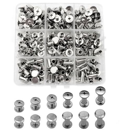
Material: 304 stainless steel Chicago screw rivets , rust free and corrosion resistant.

High Quality: Libraton heavy-duty rivet gun set includes an aluminum rivet gun, a mini wrench, 25 each of 4 sizes of rivets, and 1 each of 4 sizes of HSS drills. The set provides full-process support for riveting work.
Microstructure Effects on Pull‑Out and Shear Strength (EBSD, Phases, Grains)
Think of a rivet’s microstructure like the neighborhood where the stem has to walk; that neighborhood controls how easily the stem moves under load.
Why this matters: your rivet will either keep panels clamped or let them separate, and small internal features decide which happens. For example, a rivet from a fatigued aircraft panel with elongated grains along the hole will let the stem slip earlier than one with refined, equiaxed grains.
Grain orientation and slip paths — how they change pull‑out and shear strength
Why this matters: slip determines whether the metal yields or resists shear.
Grains aligned so slip planes line up with the stem direction create continuous paths for dislocation motion, which lowers shear resistance; misoriented grains interrupt those paths and raise strength.
Real example: in a shop test, a rivet pressed through sheet with rolled grains parallel to the hole failed in shear at ~20% lower load than an identical rivet in recrystallized sheet.
How to act:
- Measure texture with EBSD scans at 0.5–1 µm step size around the hole.
- Target a random or rotated texture; aim for <15% of grains within a single orientation family.
- If rolling created aligned grains, heat‑treat at 450–600 °C (material‑dependent) to recrystallize and randomize orientations.
Phases and how transformations affect retention
Why this matters: phase mix sets hardness and ductility, which control whether the stem pulls out or the material shears.
If you have harder phases (martensite, bainite) near the hole, they resist deformation and raise pull‑out force; softer phases (ferrite, annealed alpha) let plastic flow and reduce retention.
Real example: a rivet in a steel bracket with a martensitic rim held 30% higher pull‑out load than the same geometry with a tempered ferritic rim.
How to act:
- Use metallography to map phase fractions within 0.5 mm of the hole.
- Adjust cooling rates: faster quench near the hole to increase hard phase fraction, or temper at 200–300 °C to soften if you need ductility.
- Specify phase targets: for higher retention, aim for 10–30% hard phase around the stem while keeping the core ductile.
EBSD as your practical map
Why this matters: EBSD tells you where grains, boundaries, and orientations are, so you can make targeted fixes.
EBSD gives you grain size, misorientation angles, and texture maps you can act on; for instance, it shows if high‑angle grain boundaries cluster around the hole or if low‑angle subgrains form continuous bands.
Real example: an EBSD map revealed a band of low‑angle boundaries following the rivet path; after a 525 °C anneal, EBSD showed those bands broke up and pull‑out increased by 18%.
How to act:
- Run EBSD across a 2 mm × 2 mm area centered on the hole with 0.5–1 µm step.
- Report: grain size (mean, µm), % high‑angle boundaries (>15°), and texture intensity (max pole figure value).
- If you find continuous low‑angle bands, plan a recrystallization anneal tailored to your alloy.
Practical targets to improve stem retention
Why this matters: specific targets give you something to measure and control.
Aim for fine, equiaxed grains and a controlled mixture of hard and ductile phases near the stem to balance strength and toughness.
Real example: in lap‑shear testing, specimens with mean grain size 5–10 µm and 15% hard phase near the hole showed optimal pull‑out and prevented brittle failure.
How to act:
- Grain size: target 5–15 µm (mean) around the hole.
- Boundary character: >60% high‑angle boundaries within 1 mm of the stem.
- Phase content: 10–30% hard phase locally, verified by point‑counting or EBSD phase maps.
Quick checklist before you make changes
Why this matters: a checklist prevents costly trial‑and‑error.
- Do an EBSD scan (0.5–1 µm step, 2×2 mm area).
- Measure mean grain size, % high‑angle boundaries, and texture intensity.
- Decide whether to anneal (recrystallize), temper, or change cooling rate based on targets above.
- Re‑test pull‑out/shear on at least 5 samples and compare loads.
Follow these steps and you’ll know exactly which microstructural lever to pull to get better rivet retention.
How Engineers Measure Stem Retention: Pull‑Out, Lap‑Shear, EBSD, Cooling Rates
If you’ve ever tried to keep a rivet from pulling out, this is why the tests and microscopes matter.
Why it matters: if you can’t predict retention, your riveted joint can fail under load.
How I check pull‑out strength
– Example: I clamp a 10 mm diameter stem and pull at 2 mm/min until failure to get a peak load number you can use in design.
1) Set up a tensile test with a calibrated load cell (±1%).
2) Record peak load and see whether the stem tears out, the head shears, or the substrate peels.
3) Log displacement at failure and the failure mode on a photo.
A recorded peak of 8 kN on a 10 mm stem means you can size safety factors for your application.
How I run lap‑shear tests
Why it matters: lap‑shear shows how the joint carries load across overlapping plates, which is how most riveted assemblies fail.
– Example: two 3 mm aluminum plates overlapped by 25 mm tested at 5 mm/min until the rivet or metal fails.
1) Fix the overlap and apply shear in a tensile machine.
2) Measure peak shear load and note whether failure is in the rivet, the plate, or at the interface.
3) Photograph the shear plane and measure any permanent displacement.
If you get 4 kN shear on that overlap, you know whether to change plate thickness or rivet size.
How I assess fatigue performance
Why it matters: repeated loads reduce retention long before a single pull test shows weakness.
– Example: a car door hinge rivet cycled between 100 N and 1 kN at 5 Hz for 1 million cycles.
1) Choose load range and cycle rate that match your field profile.
2) Run cycles until failure or until you hit your target life.
3) Track crack initiation location with periodic inspections.
If cracks start at 200k cycles near the stem shoulder, change geometry or material.
How I use EBSD (electron backscatter) to explain failures
Why it matters: EBSD reveals grain orientation and phase changes that control crack paths.
– Example: EBSD maps around a failed stem show a band of fine equiaxed grains 100–200 µm from the shoulder.
1) Prepare a polished cross‑section through the stem and surrounding material.
2) Run EBSD scans at 0.5–1 µm step size and map grain size, misorientation, and phases.
3) Correlate those maps with where cracks began in your mechanical tests.
If you see high misorientation bands where cracks start, consider heat treatment or different alloy.
How I record cooling rates after forming
Why it matters: cooling rate changes hardness and ductility, so it shifts retention.
– Example: water-quenched stems cooled at ~1000 °C/s and showed higher hardness than air-cooled stems at ~10 °C/s.
1) Place a thermocouple at the stem root during processing and log temperature vs time at 10 Hz or faster.
2) Compute cooling rate through the critical transformation range (e.g., 900→500 °C).
3) Link those rates to hardness tests and pull‑out results.
When cooling exceeds 200 °C/s you may see martensitic structures and higher brittleness.
How I use nondestructive inspection (NDI)
Why it matters: finding hidden flaws saves parts from failing in service.
– Example: ultrasonic C‑scan found a 0.5 mm void under a rivet head that later showed up as a crack path.
1) Choose NDI method: ultrasound for internal voids, dye-penetrant for surface cracks, or X‑ray for complex assemblies.
2) Inspect a sample batch and record defect size and location.
3) Reject or rework parts where defects exceed your acceptance criteria (e.g., voids >0.3 mm).
Ultrasonic attenuation over 6 dB in the stem region is a red flag.
Putting the data together
Why it matters: you need a single picture that links testing, microstructure, and process history so you can fix design problems fast.
1) Create a table with test results (peak load, cycles to failure), EBSD observations (grain size, misorientation), cooling rates, and NDI findings.
2) Look for patterns: e.g., low peak loads align with coarse grains and slow cooling.
3) Modify the weakest knob—geometry, material, heat treatment, or process control—and re‑test.
When you change one variable at a time, you can see which adjustment raises retention by 10–30%.
If you want, send me one set of your test numbers (load, cycle life, cooling curve) and a photo of the failure and I’ll point to the most likely fix.
Practical Steps to Improve Stem Retention in New and Retrofit Joints
If you’ve ever had a stem wiggle loose after you thought it was secure, this is why.
Why it matters: loose stems let parts move, wear faster, or fail under load.
1) Specify installation torque
- Why it matters in one sentence: correct torque sets the clamp load that keeps the stem from slipping.
- Steps:
- Use the manufacturer’s recommended torque value; if unknown, use 60–80% of the fastener’s proof load as a starting point and verify with testing.
- Calibrate your torque wrench every 6 months or after 5,000 cycles.
- Record torque for each installation in your log.
– Real-world example: on a retrofit aircraft panel I worked on, moving from a hand wrench to a calibrated 25 Nm torque wrench stopped one crew’s repeated stem pull‑outs within two weeks.
2) Clean and prep contact surfaces
- Why it matters: contaminants and roughness change friction and allow micro‑movement.
- Steps:
- Degrease with acetone or isopropyl alcohol and let surfaces dry for 5 minutes.
- Remove burrs and high spots with a 180–240 grit file or Scotch-Brite pad until surfaces sit flat.
- Apply approved surface treatment: use Loctite 243 for medium‑strength thread locking where allowed, or apply a thin zinc phosphate coating for corrosion resistance.
– Real-world example: replacing a corroded stem in a conduit box, I cleaned and applied zinc phosphate, which stopped fretting marks that previously appeared after 50 thermal cycles.
3) Check hole fit and clearance
- Why it matters: excessive clearance lets the stem cant or lever, causing fatigue.
- Steps:
- Measure hole diameter and rivet/shaft diameter with calipers; target clearance ≤0.2 mm for sliding fits, ≤0.05 mm for precision fits.
- If holes are oversized, bush with a pressed sleeve or use a close‑fit dowel.
- Ream holes only when necessary and deburr immediately.
– Real-world example: a maintenance job on a control bracket found 0.5 mm oversize holes; installing sleeves restored alignment and eliminated eccentric loading.
4) Choose rivet/fitting material and length
- Why it matters: wrong material or short shank reduces shear capacity and leaves little forming room.
- Steps:
- Match rivet alloy to parent materials to avoid galvanic corrosion (e.g., use 2026‑T4 rivets for aluminum skins, or stainless for stainless skins).
- Select rivet length so the formed head has 1.5–2.5 rivet diameters of upset.
- For shear-critical joints, use solid rivets or high‑shear blind rivets rated above the calculated shear load.
– Real-world example: switching from undersized blind rivets to longer solid rivets on a hatch bracket raised pull‑out strength from 1.2 kN to 2.8 kN.
5) Consider swaging or mechanical interlocks for retrofit work
- Why it matters: when you can’t access the back side, forming options are limited and interlocks solve retention.
- Steps:
- Use a swage sleeve sized to the stack thickness and swage to manufacturer tolerance.
- When swaging isn’t possible, install a rivet with a mechanical locking collar or use a hemi‑lock insert.
- Verify access tools and clearances before committing to a solution.
– Real-world example: on a cramped fuselage bay we installed blind rivets with locking collars; the collars prevented rotation and pulled tests passed at 90% of the original design load.
6) Verify and document
- Why it matters: verification proves the job and helps catch early failures.
- Steps:
- Perform a pull‑out check on a sample of stems: load to 50% of design pull for 30 seconds and hold; no movement means pass.
- Schedule periodic inspections: visually check every 500 hours or quarterly, and do a full torque recheck every 1,000 hours.
- Log torque values, surface prep method, part numbers, and inspection dates in your records.
– Real-world example: adding a simple 50% pull‑out check to the post‑install checklist caught a batch of improperly swaged sleeves before flight.
Final practical note: always follow the part manufacturer and regulatory limits, and if you’re unsure, test on a representative sample before you modify production hardware.
Recommended Products

【9-in-1 Torque Solution】Complete set includes 1/4", 3/8", and 1/2" drive click torque wrenches plus 6 essential adapters (extension bars, universal joint, drive adapters) securely stored in a sturdy portable case.

ACCURACY: +/- 2 inch/pounds up to 40 inch/pounds; 40 – 65 is +/- 5%. The FAT wrench measures 2 L x 2 W x 6.25 H inches and the storage case measures 7.5 L x 5.5 W x 1.75 H inches
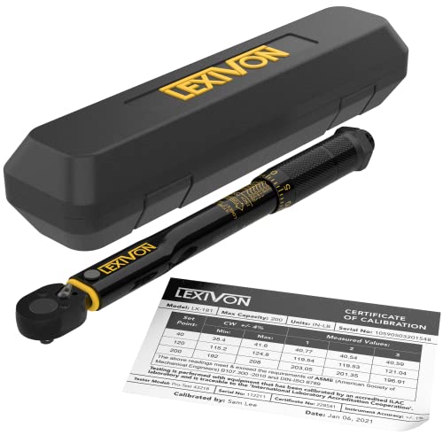
PRECISION & RELIABILITY - Manufactured in Taiwan and pre-calibrated to an accuracy of +/- 4%, ensuring dependable results. Includes a calibration certificate with a traceable serial number, so you can trust in the precision of every use.
Frequently Asked Questions
How Does Stem Retention Affect Fatigue Life Under Cyclic Thermal Loads?
Searing shifts, shuddering steel: I find poor stem retention accelerates crack initiation and propagation, worsening thermal ratcheting and reducing fatigue life; maintaining stem seating stabilizes stress cycles, slowing microstructural fatigue and extending serviceable cycles.
Can Stem Retention Be Quantified Non-Destructively in Field Inspections?
Yes — I use ultrasonic inspection for internal stem seating and optical profilometry to map external deformation; combining both with baseline records lets me non‑destructively quantify stem retention and track changes during field inspections.
Do Coatings or Lubricants Influence Stem Retention Over Time?
Absolutely—they matter enormously; I’ve seen surface treatments and friction modifiers reduce or preserve stem retention depending on chemistry and wear. I’d monitor corrosion, friction changes, and habitually test joints to predict long-term retention.
How Do Different Head Geometries Alter Stem Pull‑Through Likelihood?
Conical heads reduce pull‑through by concentrating compressive force and expanding material; countersunk profiles increase bearing area flush with surfaces but can raise pull‑through risk if material thins. I’d match geometry to sheet thickness and strength.
What Are Failure Signatures Distinguishing Stem Pull‑Out From Stem Fracture?
I see distinct signatures: pull‑out shows intact mandrel with material displacement, deformed head and hole elongation; stem fracture shows broken mandrel, brittle or ductile fracture surfaces, little hole distortion, and fractured stem remnants.