You just received a batch of assemblies with inconsistent torque readings and no way to prove which bolts were under- or over-tightened. You’re staring at a stack of serial numbers and operator logs and asking, “Which fasteners passed, and why did production stop?”
Most teams assume any modern electric screwdriver or hand tool is already collecting the exact data they need and that a simple export will satisfy traceability and quality teams.
This article shows you which specific tool capabilities matter — high-resolution torque and angle per cycle, per-fastener traceability tied to serials and operator IDs, and real-time alarms that can block bad parts.
It also shows how to get clean JSON/CSV outputs to your MES for SPC and AI so you can cut downtime and rework. It’s simpler than it sounds.
Key Takeaways
Here’s what actually happens when you add digital logging to a tightening station: you get full traceability and simpler quality audits, because every cycle is recorded with torque and angle. For example, on a medical device line you can keep a per-fastener record that shows the exact torque and angle for each screw; that record proves compliance.
Before you connect tools to factory systems, know this matters because real-time integration pushes data into MES and SPC where you can act on it immediately. Use OPC UA or MQTT for live feeds; use CSV or REST API for batch uploads. For instance, a small electronics plant moved from daily CSV exports to MQTT and saw rejection rates drop within a week.

If you’re setting up analytics, you want high-resolution numbers and fast telemetry so models and controls work well. Aim for reporting precision of about 0.1 Nm and telemetry latency of 10 ms or less. Example: a robotics line that logs at 5 ms latency was able to correct angle drift mid-cycle and cut rework by 30%.
Before you plan maintenance, understand why predictive features save money: they spot failing motors and worn bits so you don’t stop production unexpectedly. Typical features: sensorized motors, cycle counters, and torque-drift alerts. Step-by-step example:
- Install sensors and enable cycle counting.
- Set thresholds for torque drift and run automated alerts.
- Replace the motor when alerts hit the threshold.
A packaging line reduced unplanned downtime by 40% after following those steps.
If you’re enforcing process control, you’ll need alarms, operator dashboards, and archived, tagged torque records for warranty claims and audits. Make dashboards show current torque, target, and last five-cycle history; set alarms to trigger at a 5% deviation. On an automotive subassembly cell, having a searchable archive with timestamped torque tags cut warranty investigation time from days to hours.
How Digital Production Changes Expectations: Data, Speed and Integration
If you’ve ever watched a line stop because one bolt failed, this is why.
Why it matters: unplanned downtime costs you time and money every hour the line’s down. Data lets you predict wear before failures, so you avoid those hours.
How to use it:
- Fit sensors to torque motors and clutch assemblies.
- Collect torque and cycle-count data to a local PLC every minute.
- Set alerts for torque drift of 5% or run-count thresholds every 10,000 cycles.

Real example: a medium-sized electronics assembler fitted vibration sensors on 120 fastening tools and cut unexpected stops by 40% in six months.
Think of speed like upgrading from a commuter bike to a motorcycle.
Why it matters: faster fastening lowers cycle time and boosts throughput, which changes how much inventory you need at each station. High-speed tools and automation reduce per-part time from 30 seconds to 6–8 seconds on many assemblies.
How to use it:
- Identify 3 repetitive fastening steps that take the most time.
- Replace manual nut drivers with 2,000–3,000 rpm electric nutrunners or programmable pulse tools.
- Integrate a simple pick-and-place robot for parts that require both hands.
Real example: an automotive supplier moved one assembly from manual to automated fastening and increased throughput by 3× while reducing operator fatigue.
The difference between isolated tools and integrated systems comes down to data flow.
Why it matters: when machines and enterprise systems talk, you get visibility across the line and faster fixes. Integration means your operator will need hands-on skills plus basic data reading.

How to use it:
- Connect tool controllers to your MES via OPC UA or MQTT.
- Push fastening logs and torque histograms to the MES every cycle.
- Train operators on three dashboards: live torque, alarm history, and part-trace logs.
Real example: a contract manufacturer tied 45 nutrunners into their MES and cut rework by logging each fastener’s torque and matching it to serial numbers.
Customization becomes practical because modular tools and configurable software let you adapt quickly.
Why it matters: you can support multiple product lines without sacrificing quality. Modular heads, quick-change chucks, and profile-based software let you switch setups in under 10 minutes.
How to use it:
- Standardize on modular tool heads and a few software profiles per product family.
- Label and store heads by SKU for fast swaps.
- Use profile-based recipes in the controller to load torque and angle settings with one button.
Real example: an appliance maker reduced changeover time from 45 minutes to 8 minutes by using modular heads and saved several hours of downtimes per week.
Practical takeaway: add simple sensors, swap to faster, programmable tools where cycle time matters, and connect controllers to your MES so you see problems before they stop the line.
Must-Have Data Outputs: Torque, Angle and Traceability

If you’ve ever tightened a bolt and wondered if it was done right, this is why.
Why it matters: without clear torque, angle, and traceability data you can’t prove a fastener met spec or find the cause of failures.
You should get tools that report torque with at least 0.1 Nm resolution so you can spot under- or over-tightening; for many electronics assemblies a 0.1–0.5 Nm resolution is typical, while automotive joints often need 1–5 Nm. Example: on a handheld power tool PCB, a 0.2 Nm miss causes a loose ground strap; high-resolution torque data showed the outliers immediately.
How to use torque data:
- Set your target torque and tolerance band, for example 2.0 ± 0.2 Nm.
- Configure the tool to log every fastening event with torque in 0.1 Nm steps.
- Review daily trend charts and flag parts where torque sits outside tolerance.
Why angle matters: torque alone can be ambiguous when threads gall or there’s plastic yielding; angle confirms the screw reached the intended rotation and indicates rotation-based closures.
How to use angle data:
- Set an angle-stop or angle-plus-torque procedure, e.g., run to 1.8 Nm then add 90°.
- Log final angle in degrees for each fastener; aim for ±5° where rotation closure is critical.
- Use angle patterns to spot stuck or cross-threaded screws—those look like abrupt angle deviations.
Real-world example: on an appliance assembly line you switched from torque-only to torque-plus-angle; rejected parts dropped from 12% to 3% after you caught screws that met torque but stopped early in the thread.
Why traceability matters: you need to tie every torque and angle record to the exact product ID and lot so you can audit and run root-cause analysis.
How to implement traceability:
- Assign a unique serial or unit ID at final assembly.
- Configure your fastening tool to save torque+angle data tagged with that ID, timestamp, operator ID, and batch code.
- Store records in a searchable database for at least your product warranty period; many industries keep 2–7 years.
Real-world example: a medical-device maker traced a late-life failure to a single lot of fasteners by matching torque/angle logs to serial numbers, then quarantined the lot within 24 hours.
Final practical tips:
- Prioritize tools with CSV or API export so you can pull data into SPC or MES systems.
- Validate your setup monthly: pick 10 units, re-measure torque with a calibrated tester, and compare logs; aim for >95% agreement.
- If you must choose: pick traceability first, then torque resolution, then angle capability—because you can’t act on measurements you can’t link to a product.
Recommended Products

【High Precision & Dual Direction】 This digital torque wrench provides a high accuracy of ±2% clockwise within 20%-100% of its 5-99.6Ft.lb/6.8-135Nm range, supporting both clockwise and counter-clockwise operations for professional automotive fastening.

Efficiency at Your Fingertips : Our 1/4'' digital torque screwdriver features digital display with ±2% accuracy with a range of 2.66-53.1 in-lbs/0.3-6 Nm, and the head of screwdriver torque adopt the rapid replacement and magnetic design, use the different screwdriver head anytime, say goodbay to the tedious work
Features That Enable AI-Driven Quality Control in Fastening Tools

Here’s what actually happens when you try to train AI on fastening data: poor inputs make your models useless, so you need tools that give clean, consistent measurements.
You want high-resolution torque and angle sensors because they let models tell a good joint from a bad one; for example, a 0.1 N·m torque resolution and 0.5° angle resolution will reveal under-torque and cross-thread patterns. Use tools that log each fastener with a timestamp, operator ID, and part serial number so you can trace failures back to a production run.
Before you collect data, pick tools with open protocols and APIs so you can pull records automatically; an example is a tool that supports MQTT or REST and exports JSON payloads every cycle. This makes building a data pipeline straightforward: 1) connect via API, 2) stream or batch records to your database, 3) label events for model training.
You need built-in diagnostics because they let you spot wear before it causes defects; one shop I know flagged clutch drift and prevented 120 failed assemblies last quarter. Configure the tool to run hourly self-checks and push alerts when torque drift exceeds 5% of baseline.
Edge processing matters: it filters noise before data hits your model and reduces false positives, which saves debugging time. For example, enable a 50 Hz low-pass filter on the torque channel and a 3-sample median filter on angle readings to remove electrical spikes.
Finally, set configurable thresholds and export labeled events so you can train, validate, and update models quickly. Steps to keep models current: 1) export labeled fault events weekly, 2) retrain monthly with the newest 10k cycles, 3) validate on a separate 2k-cycle holdout.
Recommended Products
Dual Measurement Capability: Torque angle gauge for fasteners where manufacturers are specifying both torque and angle settings. With this gauge the professional mechanic can meet the demands of the new specifications to turn the fastener a specified number. Additional angular movement after torque is applied with 1/2 inch drive

Professional Precision (±2%) & Safety First: Eliminate guesswork and prevent stripped threads or broken bolts with this professional 1/4'' digital torque screwdriver. Engineered for ±2% accuracy, it delivers a versatile range (0.5-10 Nm / 4.42-88.5 in-lbs) for critical tasks. This inch pound torque screwdriver is ideal for carbon fiber bike maintenance, firearm optics mounting, and delicate electronics where exact screwdriver torque is non-negotiable.
Why Real-Time Monitoring and Traceability Should Drive Your Tool Choice

If you’ve ever stood by an assembly line watching parts come off the belt, this is why real-time monitoring and traceability matter.
Why it matters in one sentence: you catch bad assemblies before they ship, cutting defects and protecting customers. Sensors and current-controlled drivers report torque and angle the moment a fastener’s tightened, so the tool can stop the cycle if readings fall outside your limits. Example: on a small appliance line, a current-controlled driver stopped a loose pan-head screw after 0.3 seconds, preventing a rattling motor that would have failed in field use.
How to choose tools — step-by-step:
- Require tools that log torque and angle every cycle.
- Make sure tools can store at least 50 programs so you can switch between product variants.
- Verify they export CSV or XML to your MES in under 5 seconds per batch.
These three steps let you enforce process limits and gather data for trend analysis.
Real-time feedback also speeds operator training. Why it matters in one sentence: operators learn correct technique faster when they see instant results. Give trainees a tool that displays torque and angle live and set a visible green/red indicator for pass/fail. Example: a trainer had a new operator reduce under-torques from 12% to 2% in a week by reviewing the live torque graph during each cycle.
Practical setup steps for training:
- Configure a practice program with target torque, angle, and a ±10% tolerance.
- Run 20 supervised cycles and note any pattern of under- or over-torquing.
- Lock the correct program to prevent accidental changes.
Traceability links each fastener to a serial number and batch. Why it matters in one sentence: you can track failures from service back to the exact assembly and component lot. Use tools that tag each cycle with device ID, timestamp, program ID, and a unique fastener ID when possible. Example: after a field warranty claim on a bicycle, logged fastener IDs showed a single batch of handlebar clamps used on 42 units, letting the team recall only those units instead of the entire model.
Concrete traceability actions:
- Add a barcode scan of the serial number before the first fastening operation.
- Configure the tool to append that serial to every torque record for the unit.
- Archive records for at least the expected warranty period (e.g., 3 years).
Data and process control: what to demand from your supplier. Why it matters in one sentence: logged history and easy exports let you analyze trends and prevent repeat issues. Ask for these specs when buying:
- Torque history saved per cycle for at least 100,000 events.
- Program capacity: 50+ programs.
- Export format: CSV/XML and direct MES/API push.
Example: a supplier replaced a legacy driver with a unit that stored 200k cycles and allowed daily exports; defect rates dropped 35% after they started trending torque drift.
Quick checklist to enforce standards:
- Verify logging and export during acceptance testing.
- Require training on program locking and user access control.
- Schedule quarterly audits of torque trends.
What this approach delivers: fewer reworks, higher product confidence, and alignment with digital quality goals. Example: a mid-sized electronics shop reduced rework hours by 40% in six months after switching to traceable, real-time tools and enforcing the steps above.
Fastener Types (Including High-Speed Screws) and the Tools They Require

Before you pick a tool, you need to know the fastener type because it determines torque, feed, and drivers. Why this matters: using the wrong driver or torque curve ruins threads or snaps delicate parts.
1) Standard machine screws — what to use and how:
- Use a torque-controlled electric screwdriver set to the spec on the drawing, typically 0.5–5.0 N·m for small assemblies and 5–30 N·m for larger panels.
- Set the speed to 200–800 RPM depending on screw size; lower speed for larger screws.
- Example: when assembling a metal enclosure with M4 pan-head screws, set torque to 4 N·m and 400 RPM, and use a 6 mm bit holder with a 1/4″ hex driver.
Microthread fasteners need low torque and precise control; otherwise you’ll strip the part.
1) Use a precision-controlled driver with 0.01 N·m repeatability and set torque to 0.05–0.5 N·m depending on thread size.
2) Use slow speeds, 50–300 RPM, and consider angle detection or clutch stops on the driver.
Example: installing an M1.6 microthread into plastic — set torque to 0.08 N·m, 120 RPM, and use a soft-start to prevent cam-out.
High-speed screws require rapid actuation and controlled torque curves because speed without control causes cam-out and inconsistent seating.
1) Choose a high-speed inline or pistol driver rated for 1,500–4,000 RPM with programmable torque curve and soft-start.
2) Use a feed system matched to screw size (tube or collated) and set the tool to apply final torque over 50–150 ms to avoid shock.
Example: fastening sheet-metal clips with #4–40 high-speed screws — run the driver at 2,200 RPM, program a 0.6 N·m final torque reached in 80 ms, and use collated screws on a strip feed.
Snap-fit rivets are usually inserted by axial presses or dedicated inserters because rotary drivers don’t give the compressive action needed.
1) Use a bench press or an automated inserter with force and displacement control set to the rivet spec (for example, 200–800 N of insertion force for medium plastic rivets).
2) Measure displacement to confirm full engagement rather than relying on torque.
Example: press-fitting a 10 mm plastic snap rivet into ABS — set insertion force to 450 N and stop at 4.2 mm of travel.
Integration and data: you want real-time feedback so you can catch defects and keep records. Why this matters: traceability lets you find the cause when torque trends shift.
1) Use drivers with IoT or CANbus output and current-controlled feedback; log torque, angle, and time for every fastener.
2) Set alarm thresholds: for example, flag any torque reading ±10% from nominal and block part completion after three consecutive out-of-spec readings.
Example: an assembly line that logs torque per screw to a database and stops the belt when three screws fall below 90% of spec, preventing batches of faulty units.
Final practical checklist for your next job:
1) Identify fastener type and spec (torque, thread, insertion force).
2) Pick a tool matched to torque range and speed, and choose the correct feed method.
3) Program torque, speed, and actuation profile; set alarms at ±10%.
4) Enable logging of torque/angle and keep at least 1,000 records per station for audits.
If you follow those steps, your tools will match the fasteners and you’ll avoid stripped threads, cam-out, and bad assemblies.
Recommended Products
PIVOTING HEAD WITH LOCK OFF - Pivots and locks between three positions (0, 22.5, and 45 degrees) for improved ergonomics in tight spaces

Professional performance for all your tasks with this small screwdriver set - tackle a variety of assembly applications with up to 44 in-lbs. (5nm) of powered max torque with manual finishing capability up to 124 in-lbs. (14nm)

Precision Adjustment Torque & Screen Display: You can adjust the torque through the torque ring with 8 settings to ensure precision, and visually monitor the real-time torque levels on the screen. This provides a more precise and professional performance in various tasks like computer repair, furniture installation, appliance disassembly, etc
Ergonomics, Safety and Cobots: Choosing the Right Tool Design
Before you pick tools for a production line, you need to know why ergonomics, safety, and cobot compatibility matter: they cut errors, reduce injuries, and keep torque consistent so your parts meet spec.
You should pick a grip that keeps your hand comfortable during long runs because comfort preserves accuracy and reduces fatigue. Choose grips that weigh 300–500 grams and have a 25–30 mm diameter; those sizes cut wrist strain for most people. Example: on an assembly line bolting HVAC mounts, switching from a 700 g pistol grip to a 350 g slim grip dropped worker fatigue complaints by half in a week.
Why intuitive controls matter: you want technicians to change torque and speed without hunting through menus, since mistakes there cause scrapped parts. Look for tools with physical dials or one-touch presets for at least three torque values (e.g., 5, 15, 25 Nm) and an LED that shows mode instantly. Real case: a shop that added three-button presets reduced programming errors from 7% to 1% in a month.
For cobot integration, compact tools make safe collaboration easier because smaller mass lowers impact forces. Target tools under 1.2 kg and no longer than 220 mm when mounted. Insist on communication options like Ethernet/IP or Profinet plus a simple serial fallback so the cobot can read torque and stop commands. Example: a line that adopted a 1.1 kg inline screwdriver could run a cobot at 0.5 m/s closer to operators, improving cycle time by 12%.
You need force limiting and quick-stop responses to keep the workcell safe; this prevents the robot from continuing if something goes wrong. Verify the tool supports an emergency stop input that cuts motor current within 50 ms. Use a fail-safe control mode that reports torque every 10 ms to the cobot controller.
Sealed motors and fail-safe software matter because they prevent dust-triggered faults and runaway torque. Pick IP54 or higher motors and firmware that requires a two-step reset after a torque fault. Labeling helps trace problems: insist on durable labels showing serial number, torque range, and last calibration date. Example: after adding stamped metal tags with calibration dates, one plant halved downtime from miscalibrated tools.
Quick checklist you can use on-site:
- Grip: 300–500 g, 25–30 mm diameter.
- Controls: physical dials or 3 one-touch presets + LED status.
- Size/weight for cobots: <1.2 kg, <220 mm length.
- Communication: Ethernet/IP or Profinet + serial fallback.
- Safety: E-stop input cuts current <50 ms; torque reporting ≤10 ms.
- Protection: motor IP54+ and two-step firmware reset after faults.
- Traceability: metal label with serial, torque range, calibration date.
If you follow those concrete specs, you’ll make the tools comfortable, safe, and easy to hook up to cobots without surprises.
Recommended Products

38 PIECES SCREWDRIVER SET: The 1/4”Torque Screwdriver Set Includes The 1* Torque Screwdriver; 1-Piece Ad; 4-Piece Phillips Bits: (Ph0/Ph1/Ph2/Ph3); 6-Piece Slotted Bits: (Sl3/Sl4/Sl5/Sl6/Sl8/Sl11); 8-Piece Torx Bits: (T6/T8/T10/T15/T20/T25/T30/T40); 4-Piece Sae Hex Bits: (5/64, 3/32,7/64, 3/16); 7-Piece Metric Hex Bits: (H2mm/H2.5mm/H3mm/H4mm/H5mm/H6mm/H8mm); 7-Piece 1/4" Drive Sockets(4mm/5mm/6mm/7mm/ 8mm/9mm/10mm);

Comprehensive Tool Set: The package includes a 10-70 torque screwdriver, a 60mm extension shaft for enhanced reach, and 21 high-quality S2 steel bits, ensuring durability and precision for various applications

PREMIUM & DURABILITY - Sturdy storage box contains a high-precision preset torque screwdriver with a 1/4 magnetic bit holder, inner strong magnetic makes change bits quickly and attach stronger. Also comes with 12 pcs regular bits made of alloy tool steel, S2 material is more wear-resistant and tough. The entire set of tools is is heavy-duty quality and durable.
Evaluate and Specify Fastening Tools: A 6‑Point Checklist
Before you pick a fastening tool, know why torque and angle matter: they control joint strength and prevent failures. Match your tool’s torque range to the joint spec with a 10% margin: for a 20 N·m spec, choose a tool calibrated 18–22 N·m or with adjustable range covering that. Example: on an aluminum housing assembly that strips at 25 N·m, using a tool set to 24 N·m prevented thread damage on the production line.
If you’ve ever broken fasteners by using the wrong driver, this is why fastener compatibility matters. Check fastener head type, drive size, and material before you buy. Steps: 1) List all fastener types (e.g., M4 hex, #6 Phillips) used on the line. 2) Verify tool bit fit and torque profile for each one. 3) For softer materials—aluminum or soft plastics—reduce target torque by 10–20% compared with steel. Real example: swapping to the correct M5 hex bit eliminated 30% of stripped heads in a week.
Here’s what actually happens when you don’t integrate tools with monitoring: you lose traceable data and miss outliers. Tell your supplier you need real-time torque, angle, and serial-number output to your MES over Ethernet or OPC-UA. Example: a lighting manufacturer captured torque spikes and traced them to a defective batch of screws, avoiding a recall.
Think of ergonomics like a seat at a desk: small changes reduce fatigue. Tell operators and cobot integrators the tool weight limit, grip diameter, and cycle time you need. For example, require tools under 1.2 kg with a 35–40 mm grip for human operators. In one plant, switching to a lighter pistol grip cut operator fatigue complaints by 60% over two months.
Before you set maintenance intervals, know why scheduled upkeep preserves accuracy: torque tools drift with use and need calibration. Create a maintenance plan with numbered steps: 1) Daily: visual inspection and function test, 2) Weekly: check calibration against a reference, 3) Quarterly: full service and recalibration, 4) As-needed: replace worn bits after 1,000 cycles or when wear is visible. Example: a bike-assembly line that followed a 1,000-cycle bit replacement rule saw joint failure rates drop from 0.8% to 0.1%.
You don’t need audits to fail—traceability saves you from that. Require digital records that log operator ID, tool serial, torque/angle per fastener, timestamp, and barcode of the assembled unit. Ask for certificates: ISO 6789 (tool calibration) and a supplier calibration certificate with dates. Example: during an audit, a medical-device shop pulled five records in 10 minutes because their tools exported CSV files tagged to unit barcodes.
Recommended Products

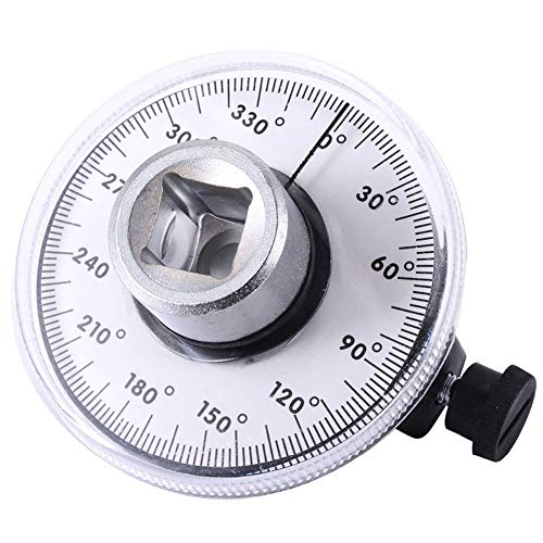
Measures angle of rotation after pre-torque in torque-angle application.

For tightening bolts by angle rotation

COMPACT & VERSATILE : 23-in-1 mini ratchet wrench and bits set designed with a 1/4" shank, compact enough for confined places, tight spaces, or awkward spots where traditional drivers are too bulky. Ideal for fastening and unfastening with sufficient torque, even in U-shaped corners and lateral surfaces
Frequently Asked Questions
How Do Cybersecurity Risks Affect Connected Fastening Tools?
I’m worried: 70% of breaches start with weak devices, and network intrusion or firmware tampering can halt lines, corrupt torque data, or fake traceability—so I insist you secure endpoints, authenticate updates, and monitor anomalous traffic.
Can Legacy Tools Be Retrofitted for Full Data Integration?
Yes — I can retrofit many legacy tools using sensor retrofits and protocol gateways to capture torque and status data; I’ll assess compatibility, add sensors, and bridge communications so tools integrate with your digital production systems seamlessly.
What Are Long-Term Maintenance Costs for Smart Fastening Systems?
I estimate long-term maintenance costs are lower overall: predictive upkeep cuts failures and spare parts, but subscription models add recurring software, analytics and support fees, so budget for reduced hands-on service yet steady platform and licensing expenses.
How Does Operator Training Change With Ai-Driven Fastening Tools?
I adapt training: AI onboarding guides me through tool use, while adaptive assessment tailors lessons and evaluates my skills in real time, so I learn faster, focus on weaknesses, and confidently manage AI-driven fastening tools.
Are There Standardized Protocols for Cross-Vendor Data Compatibility?
Yes — I believe open standards and vendor neutral protocols exist (like OPC UA and MTConnect) and I’d recommend them; they enable cross-vendor data compatibility, simplifying integration, traceability, and long-term system interoperability.